Introduction
Parallel database architectures have undergone significant advancements over the past four decades, transitioning from shared memory architecture to shared disk architecture and, finally, to the more efficient shared-nothing architecture. Databases designed specifically for cloud environments incorporate elements of shared-disk and shared-nothing architectures.
Teradata is a powerful and scalable relational database management system designed to efficiently handle large volumes of data and complex queries. One key feature of Teradata is its shared-nothing architecture, which is vital to the system’s linear scalability and performance. In this chapter, we will explore the shared-nothing architecture of Teradata and its benefits.
What is the Teradata Shared-Nothing Architecture?
A shared-nothing architecture is a distributed computing architecture in which each node in the system operates independently, with no sharing of resources between nodes. Each node has its own CPU, memory, and disk storage, and nodes communicate with each other via a high-speed network connection.
The advantage of a shared-nothing architecture is that it allows the system to scale horizontally, meaning that additional nodes can be added to the system to increase its capacity. This is in contrast to a shared-everything architecture, where all nodes share the same resources, which can lead to bottlenecks and performance issues as the system grows.
In a shared-nothing architecture, each node is responsible for a subset of the data, and nodes communicate with each other to coordinate their actions. This makes the system highly available, as individual nodes can fail without affecting the overall system. In addition, because each node has its own resources, the system can be more fault-tolerant, as a failure in one node does not affect the operation of other nodes.
Overall, shared-nothing architecture is a highly scalable, highly available, and fault-tolerant architecture well-suited for large-scale distributed computing applications. It is commonly used in web applications, data processing systems, and other distributed systems.
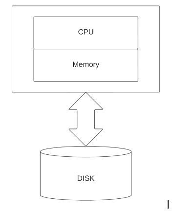
The data of each table is distributed across all nodes, and queries are executed in parallel across multiple nodes, each processing a portion of the data. This architecture allows for high scalability and performance, making shared-nothing systems ideal for large-scale data warehousing and analytics.
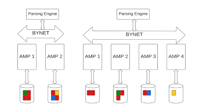
In a Teradata system, each node executes many Access Module Processors (AMPs) responsible for storing and retrieving a portion of the table’s rows.
Data distribution across the AMPs is done using hashing. A typical Teradata system has hundreds of AMPs per node.
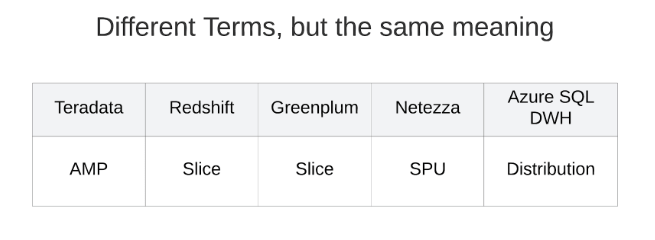
Teradata is widely regarded as the grandfather of all shared-nothing systems, with its innovative architecture that has laid the groundwork for many modern Massively Parallel Processing (MPP) systems. Subsequent database systems, such as Greenplum, Amazon Redshift, Azure SQL Data Warehouse, and Netezza, have built on this architecture, adopting similar principles but using different terminology for their components. Despite the differences in terminology, the underlying principle remains the same.
Limitations of the Shared Nothing Architecture
When adding AMPs to a Teradata system, the existing data must be redistributed across the old and new AMPs. This process is known as rebalancing and is needed to ensure that data is distributed evenly across all AMPs. Why this is crucial we will discuss later when talking about skew.
During the rebalancing process, data must be moved from existing AMPs to new AMPs, which can take a significant amount of time and impact system availability and performance.
The time required for rebalancing increases as the number of AMPs in the system grows. Scaling usually requires downtime (still, the rebalancing process can be delayed with some great features to a point in time after the system upgrade took place).
While Teradata is designed to be a scalable system, there are major limitations to its possibilities regarding scalability compared to a shared-data architecture system.
One of the key disadvantages of Teradata is that it requires scaling compute and storage together. This means that if a user needs to increase either compute power or storage capacity, they must upgrade both components simultaneously, even if only one is necessary. This lack of flexibility can lead to inefficient resource utilization and higher costs, as organizations may end up paying for additional resources they do not currently need.
Teradata is aware of this limitation and has made efforts to address it through the introduction of the Teradata Vantage Cloudlake system. This solution serves as an improvement to provide more flexibility in scalability, allowing the system to compete better with other cloud databases featuring shared data architectures (such as Snowflake). While the Teradata Vantage Cloudlake system does help bridge the gap, this approach is more of a compensatory measure rather than a complete resolution to the inherent constraint of scaling compute and storage together in Teradata’s traditional shared-nothing architecture.
Teradata Vantage Cloudlake combines a traditional Teradata system with separate compute cluster(s) utilizing a shared data layer with near-real-time scaling capabilities using the functionality Amazon, Google, or Microsoft Clouds offer. Although this innovative approach provides more flexibility for different workloads, it comes with additional complexity and administration effort.
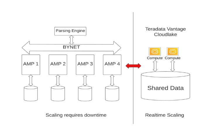
Managing and maintaining two distinct systems—the traditional Teradata architecture and the separate compute cluster(s)—requires greater coordination and oversight. This may increase operational costs and a steeper learning curve for database administrators, who must become proficient in managing both environments. Furthermore, integrating the shared data file system (object store) with the traditional Teradata file system can be challenging. Joins, for example, can only be done when both tables are located on the Teradata Cluster or the Compute Cluster. Depending on the table’s location (compute cluster or Teradata cluster), execution plan steps will be processed exclusively on one system, or tables will be moved before a join operation can occur.
Teradata, which has long advocated for its shared-nothing architecture as the best choice for strategic workload, has recently suggested a shift in its approach. The company now recommends moving large tables associated with strategic workloads to easily scalable compute clusters while using the traditional Teradata system for tactical workloads and smaller amounts of data.
The shift in Teradata’s approach is particularly intriguing because implementing tactical workloads has always been challenging on their shared nothing platform. Traditionally, Teradata’s strength has been its ability to scan and process large amounts of data quickly and efficiently.
While the Teradata Vantage Cloudlake system offers a valuable solution for organizations seeking the benefits of a more flexible and scalable infrastructure while retaining the robust features and capabilities of traditional Teradata systems, only the future can show if Teradata moves in the right direction with its hybrid architectural approach.
Benefits of Shared-Nothing Architecture
Linear scalability
Shared-nothing architectures are highly scalable, allowing new nodes to be added to the system and increasing the theoretical performance linearly. Adding four nodes to a four-node system theoretically doubles performance; however, it is important to remember that this is only the case when the entire system is perfectly tuned, which may never truly be achievable.
Performance
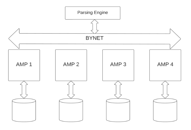
Teradata can scan huge amounts of data efficiently by utilizing parallel processing across multiple Nodes and AMPs. Teradata’s implementation of the shared-nothing architecture also provides a high level of fault tolerance. The figure below depicts the Teradata Architecture and its components we will discuss in detail next.
Components of the Teradata Architecture
The Parsing Engine
The Parsing Engine (PE) is a critical component of the Teradata system, responsible for receiving and validating user requests, generating execution plans for queries, query optimization, and query dispatching. This component’s function is essential to the performance of the Teradata system, as it is responsible for parsing, validating, and optimizing SQL queries to produce the most efficient execution plan.
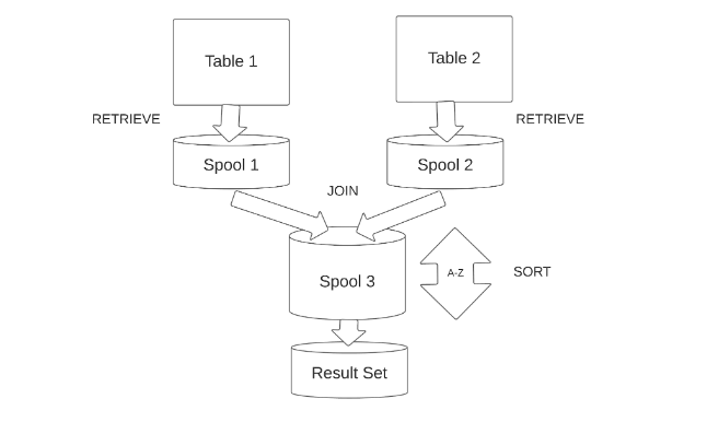
When a user submits a SQL query to Teradata, the Parsing Engine receives the query, validates the syntax, and creates a parse tree of the query components. The Parsing Engine then converts the parse tree into a query execution plan by selecting the most efficient one based on the available system resources and data demographics. The execution plan is a step-by-step guide that outlines how the query will be executed, including the tables to be accessed, the order in which the tables are accessed, which indexes are used, and the join strategy used to access the data.
The Teradata Optimizer
The Teradata Optimizer is an integral part of the Parsing Engine that performs query optimization. The optimizer uses a cost-based approach to determine the most efficient query plan based on the available system resources and data distribution.
A cost-based query optimizer evaluates different execution plans for a given query and selects the one with the lowest estimated cost, which typically corresponds to the fastest execution time. It relies on various factors, such as statistics and system resources, to estimate the cost of each potential plan.
In contrast, a rule-based query optimizer follows a predefined set of rules or heuristics to determine the execution plan without considering the actual data or system resources. These rules are often based on general best practices or established patterns rather than specific data or system characteristics.
The Teradata optimizer will not create all possible plans but a limited subset of the most promising execution plans according to the information available:
- Statistics, data demographics, and data distribution:
The Optimizer uses statistics, such as row counts, data distribution, column uniqueness, data skew, and data sparsity, to estimate the cost of different query plans. Data demographics, including data distribution as an important metric, are derived from these statistics and are used to assess the impact on query performance and optimize parallel processing across AMPs. - Index information:
Information about primary, secondary, and join indexes helps the Optimizer determine the most efficient access paths for the query. - Partitioning schemes
The Optimizer evaluates the impact of different partitioning schemes, such as row and column partitioning, on query performance. - System resources
The Optimizer considers the available system resources, such as CPU, I/O, and memory, to ensure the execution plan does not exceed the limits.
The execution of query processing steps can be classified as Serial and Parallel Steps. These classifications dictate the order and manner in which the steps are carried out and are determined by the Teradata Optimizer.
Serial Steps necessitate a strict sequential execution, where each step must be completed by all relevant Access Module Processors (AMPs) before the subsequent step is dispatched. In contrast, Parallel Steps involve multi-AMP processing steps that can be transmitted to the AMPs and completed asynchronously. However, all Parallel Steps must successfully conclude before the next Serial Step is dispatched.
Within a Multi-Statement Request, the processing steps generated can be categorized as Individual Steps and Common Steps. Individual Steps are unique to a single SQL statement in the request, whereas Common Steps comprise steps that can be utilized by more than one statement. A prime example of a Common Step is creating a Spool file whose contents can be employed multiple times.
In the presence of certain optional features, additional processing steps may be necessitated for effective query execution. The Teradata Optimizer is pivotal in determining the most efficient execution plan, considering the available resources, the database structure, and the query’s complexity.
Once the execution plan is determined, the Parsing Engine dispatches the query to the Access Module Processors (AMPs) responsible for data retrieval and manipulation. The Parsing Engine also monitors query execution, tracking the query progress and returning query results to the user.
In summary, the Parsing Engine is responsible for receiving and validating user requests, generating execution plans for queries, query optimization, and query dispatching.
The BYNET
The BYNET is the backbone of Teradata’s database, facilitating seamless communication between its components. Comprising multiple virtual processors, Teradata relies on the BYNET for interaction between parsing engine processes and Access Module Processors (AMPs), ensuring efficient query executions.
In on-premise Teradata Systems, the BYNET is responsible for communication between and within a single node through software BYNET and between nodes through a hardware BYTNET.
In cloud implementations of Teradata, such as Microsoft Azure and Amazon Web Services, and the Google Cloud, the BYNET is virtualized, leveraging the existing network infrastructure of the cloud to facilitate the Messaging Layer. Although modern Teradata hardware has replaced the proprietary switching fabric with InfiniBand (™), it’s worth noting that the term “BYNET” continues to be used historically.
Facilitating Communication and Load Balancing
The BYNET is a high-speed network connecting all Teradata system nodes, enabling efficient data distribution and queries. As a shared resource, multiple nodes can use the network simultaneously. The BYNET operates using a two-layer network topology, with a primary and backup BYNET connected to each node, ensuring fault tolerance in case of hardware or network failures.
When both BYNETs function without errors, they operate simultaneously to boost performance. Should one BYNET fail, the other enables the system to continue operating.
Key Capabilities of the BYNET
The BYNET enables effective coordination among AMPs working in parallel on the same query, both between nodes and within a single node. The Parsing Engine determines the best AMPs to execute the query based on data distribution and system resources, sending the query to the selected AMPs via the BYNET. This ensures that the query is distributed evenly across the system, maximizing load balancing and overall performance.
Fault-Tolerant Design
The BYNET’s fault-tolerant design uses redundancy and failover mechanisms to maintain system operations in case of hardware or network failures. The backup BYNET acts as a failover mechanism in case of primary BYNET failure, ensuring system reliability. The software BYNET within a single node also contributes to the fault-tolerant design.
Final Answer Set Ordering
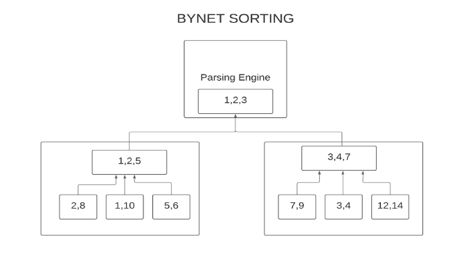
One of the unique features of BYNET is its ability to return very large sorted answer sets effortlessly. In most database systems, sorting a large final answer set is costly due to the need for several sub-sorts and data merges. This process can be I/O-intensive and time-consuming, often involving the writing and reading of intermediate data sets.
The BYNET is aware of the parallelism of the AMPs and recognizes that each AMP has built up a small sorted answer set in a buffer for its portion of the data at the end of a query. The BYNET reads the data from all AMPs simultaneously while maintaining the specified sorted order. The BYNET pulls data off the AMPs. The answer set emerges in sorted order and is returned to the client without ever having to land anywhere for one big sort/merge operation. This elegant and efficient compilation of the final answer set across parallel units bypasses I/O-intensive routines and speeds up query completion.
The AMP
Access Module Processors (AMPs) are the heart of the Teradata architecture. Understanding the AMP’s role in the Teradata system is essential for optimizing the system’s performance and ensuring efficient data access.
An AMP is a process in the Teradata system responsible for data storage and retrieval and some other auxiliary tasks. Each AMP is responsible for a portion of a table’s data, with data distribution across the AMPs done using hashing.
Each AMP operates independently, managing its exclusive storage known as a virtual disk (VDisk), a collection of Physical disks (PDisk) assigned to a specific AMP. A PDisk is simply a slice of Logical Unit Numbers (LUN) constructed on top of a group of disks (nowadays solid-state drives) arranged in RAID arrays or farms. This architecture allows for the parallel processing of queries across multiple AMPs, greatly improving query performance and scalability.
Design of a Teradata AMP
When a query is submitted to Teradata, the Parsing Engine determines which AMPs are required to execute the query.
The Parsing Engine then sends the execution plan steps to the selected AMPs via the BYNET, and each AMP executes its steps in parallel with the other AMPs. The AMPs use hashing, internal indexes, and binary search to locate the required data efficiently, minimizing the need for disk I/O operations.
AMP failures
When an AMP fails, Teradata’s fault-tolerance features and architecture ensure that data remains available and the system continues to operate. The main mechanism for handling AMP failures is called “fallback,” which involves data redundancy across multiple AMPs.
Fallback is a Teradata feature that creates and maintains duplicate copies of data rows on different AMPs. When a table is defined with fallback protection (which is always the case since Teradata Vantage), each data row inserted into the table is automatically replicated and stored on another AMP. This ensures that if one AMP becomes unavailable due to a failure, the system can continue processing queries using the redundant data on the fallback AMP.
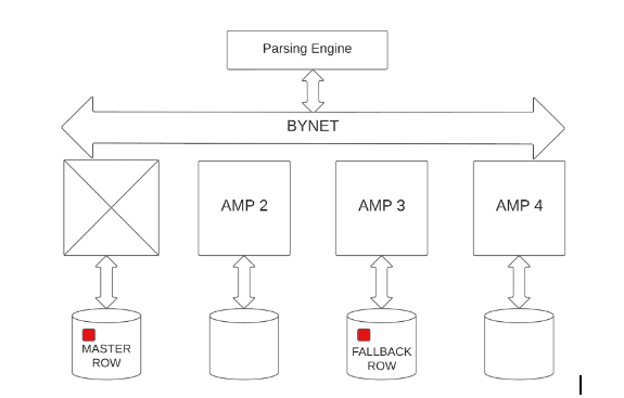
Teradata continuously monitors the health of all AMPs in the system. When it detects an AMP failure, the system automatically initiates the process of migrating the affected AMP’s workload to the fallback AMPs.
Also, Teradata’s BYNET communication layer is vital in redistributing the workload among the remaining AMPs. Upon receiving a query, the parsing engine redistributes the work to the fallback AMPs with redundant data copies.
During the AMP migration process, Teradata re-routes queries that the failed AMP would have processed to the fallback AMPs. This ensures that queries continue to execute seamlessly without affecting the system’s performance.
When an AMP fails, Teradata initiates a recovery process to bring the AMP back online. During this process, the system restores the data from the fallback AMPs to the recovered AMP and synchronizes it with the rest of the system.
Once the recovery process is complete and the failed AMP is back online, Teradata resumes normal operation, distributing the workload among all AMPs, including the recovered AMP.
Fallback, combined with Teradata’s fault-tolerant architecture, ensures that the system remains highly available and continues to process queries even in the event of an AMP failure. This mechanism allows Teradata to maintain performance and data availability with minimal disruption.
The AMP Worker Tasks
AWTs are the heart of the AMP, responsible for executing tasks and ensuring the smooth functioning of the system. AWTs are threads that process incoming tasks in the AMP. Each AMP has a finite pool of AWTs, which is shared among all the tasks that the AMP needs to execute.
When a request is received, the Parsing Engine (PE) breaks it down into steps, which are then assigned to the appropriate AMPs. Each AMP allocates an AWT from its pool to execute the assigned task. Once the task is completed, the AWT is released back into the pool, making it available for other tasks.
Efficient management of AWTs is critical to the overall performance of a Teradata system. Since the number of AWTs in an AMP is limited, poor AWT management can lead to bottlenecks and degraded system performance. The following factors contribute to efficient AWT management:
AWT Allocation: The Teradata system allocates AWTs based on priority levels, ensuring that higher-priority tasks are processed first. This helps maintain optimal system performance and prevents low-priority tasks from monopolizing the available AWTs.
Workload Management: Teradata offers advanced workload management tools, such as the Teradata Active System Management (TASM) and the Teradata Integrated Workload Management (TIWM), which enable administrators to monitor and manage AWT usage. These tools help balance workloads, assign appropriate priorities, and prevent AWT exhaustion.
AWT Tuning: Teradata provides various configuration settings that allow administrators to fine-tune AWT usage. Adjusting these settings can help optimize system performance and prevent AWT-related issues.
Monitoring: It is essential to monitor AWT usage regularly to identify potential bottlenecks and take corrective action before they impact system performance. Administrators can use tools like Teradata’s ResUsage to monitor AWT usage closely.
Message Queuing in Teradata AMPs
When an AMP receives a message, it places the message in a queue to be processed by an AWT. Each AMP has separate message queues based on the priority levels, ensuring that higher-priority tasks are handled first. The main types of message queues in a Teradata AMP are
Expedited Queue: This queue holds high-priority messages that require immediate attention, such as transaction control messages.
Work Queue: This queue stores standard priority messages, including data retrieval, storage, and manipulation tasks.
Delayed Work Queue: This queue contains lower-priority messages, such as maintenance tasks or background processes, that can be deferred.
The AWTs in an AMP pick messages from these queues based on their priority level and execute the tasks associated with them. Once an AWT becomes available, it selects the next message from the highest-priority queue with messages waiting for processing.
Congestion Control
When an AMP’s message queue is full, it can no longer accept new messages, leading to a bottleneck in the system. A full message queue can occur for various reasons, such as insufficient AWTs, inefficient workload management, too many loads running in parallel, or a sudden spike in query volume.
Teradata can avoid the serious consequences of database congestion because of the intelligence of BYNET. Each AMP works independently on its share of the work, but sometimes query work can be uneven across AMPs. An AMP experiencing a heavier load may sometimes need to catch up.
When an AMP lacks an available worker task of the required type, the tasks accumulate in a message queue. As this message queue has limited memory, the AMP notifies the parsing engine once the queue reaches capacity.
In response, BYNET temporarily stops delivering messages to the AMP. Consequently, the parsing engine cancels the task across all AMPs and retries after a brief interval (in the millisecond range). This process repeats until the AMP frees up worker tasks for the specific task. With each attempt, the waiting time between subsequent attempts increases. This mechanism, known as flow control mode, generally impacts the overall performance of the Teradata system.
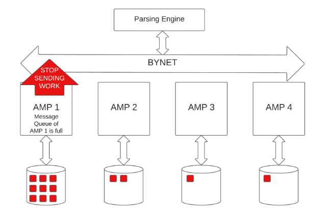
Impact on System Performance: A full message queue can significantly impact overall system performance, as it can cause delays in processing tasks and increase query response times. In extreme cases, it can even lead to query timeouts and failures.
Then as soon as the AMP has worked off its backlog, BYNET messages automatically flow again. The BYNET regulates message sending to prevent overloading a single AMP, thus protecting the throughput of the entire platform. The key advantage this approach offers is scalability.
Monitoring the Flow Control Mode
The DBC.ResUsageSAWT table in Teradata is the primary tool for analyzing the system workload in relation to the flow control state. It provides a snapshot of various metrics at specific intervals to help monitor the system’s performance. In this article, we will examine the key features of the DBC.ResUsageSAWT table and how they can monitor flow control mode in Teradata.
Main characteristics of DBC.ResUsageSAWT table:
Most of the metrics in this table represent the status at the end of a 10-minute snapshot interval, although the database administrator can change the interval.
The granularity of the data is one row per Date, Time (every 10 minutes), Node, and AMP.
Essential columns and their content:
TheDate and TheTime: Represent the date and time when the snapshot was taken, respectively, showing the status of the AMP worker tasks at the end of each 10-minute interval.
Secs: Specify the duration of the snapshot interval.
VPROCID: Identifies the AMP.
MailBoxDepth: Displays the number of messages in the AMP queue at the end of the snapshot interval. Tasks are queued when no AMP worker task is available to take over additional work.
FlowControlled: Indicates whether the AMP is in a flow control state at the end of the snapshot interval.
FlowCtlCnt: This shows the number of times the AMP entered the flow control state during the snapshot interval.
InUseMax: Displays the maximum number of AMP worker tasks active simultaneously during the snapshot interval.
Available: Indicates the number of free AMP worker tasks at the end of the snapshot interval.
AvailableMin: Displays the minimum number of free AMP worker tasks during the snapshot interval.
AWTLimit: This shows the total number of AWTs in the system.
WorkTypeMax00 to WorkTypeMax15: Show the maximum number of AMP worker tasks per work type during the snapshot interval. These columns can be renamed for better understanding.
Below is an SQL query to analyze the worst flow control situation in the DBC.ResUsageSAWT table by focusing on the AMP with the longest time spent in the flow control state on a particular day:
SELECT
TheDate
,TheTime
,Secs
,VPRID as TheAMP
,MailBoxDepth
,FlowCOntrolled
,FlowCtlCnt
,InUseMax
,Available
,AvailableMin
,AWTLimit
,WorkTypeMax00 AS DispatcherStep
,WorkTypeMax01 AS Spawned_Level1
,WorkTypeMax02 AS Spawned_Level2
,WorkTypeMax03 AS InternalWork
,WorkTypeMax04 AS Recovery
,WorkTypeMax08 AS ExpeditedDispatcherStep
,WorkTypeMax09 AS ExpeditedSpawned_Level1
,WorkTypeMax10 AS ExpeditedSpawned_Level2
,WorkTypeMax12 AS AbortStep
,WorkTypeMax13 AS SpawnedWorkAbort
,WorkTypeMax14 AS UrgentInternalWork
,WorkTypeMax15 AS MostUrgentInterbalWork
FROM DBC.ResUsageSAWT
WHERE (TheDate,NodeId,VPRID) IN
(SELECT TheDate,NodeId,VPRID FROM DBC.ResUsageSAWT
WHERE FlowCtlTime = (SELECT MAX(FlowCtlTime) FROM DBC.ResUsageSAWT )
);
Monitoring flow control mode in Teradata involves examining several key measures in the DBC.ResUsageSAWT table, such as InUseMax, Available, AvailableMin, MailBoxDepth, FlowControlled, FlowCtlCnt, and FlowCtlTime. By utilizing these measures together, you can gain valuable insight into the load and performance of your Teradata system.
Flow control mode can lead to significant performance issues if it occurs frequently and for extended durations. Occasional instances of flow control lasting only a few seconds are generally acceptable.
It is essential to analyze frequent flow control situations in detail that persist for extended periods.
Here is another simple test query that provides comprehensive information about flow control in a Teradata system:
SELECT
   TheDate
   ,TheTime
   ,MAX(WorkTypeMax00)    AS max_wrk0
   ,MAX(WorkTypeMax01)    AS max_wrk1
   ,MAX(MailBoxDepth / CollectIntervals)
   ,SUm(FlowControlled)
   ,MAX(FlowCtlCnt)
FROM DBC.ResusageSAWT
WHERE TheDATE BETWEEN DATE'2023-06-01′ AND DATE
GROUP BY  1,2
Above query retrieves, for each sample period (i.e., at the end of the period), the maximum number of tasks for the types “new task” and “continued task,” the size of the job queue, the number of flow control events, and the maximum concurrent flow control events that took place during the sample period.
Control over the flow of work occurs deep inside the database. Each AMP independently works with the BYNET to manage itself, with little overhead and no coordination with other AMPs. The number of AMPs can increase hugely, and congestion control works as efficiently.
Teradata administrators must regularly monitor AWT usage and message queue levels to prevent message queues from becoming full and maintain optimal system performance. They can employ workload management tools like Teradata Active System Management (TASM) or Teradata Integrated Workload Management (TIWM) to balance workloads, assign appropriate priorities, and manage system resources effectively. Additionally, tuning AWT configurations and optimizing query performance can help alleviate the risk of full message queues and ensure smooth system functioning. In Teradata, tactical queries are short, time-critical queries that require swift processing to support real-time decision-making and operational tasks. Teradata provides reserved AMP Worker Tasks (AWTs) specifically for these queries to ensure that tactical queries receive the necessary processing resources and complete quickly.
Reserved AMP Worker Tasks for Tactical Queries
Teradata allows administrators to configure a portion of the AWT pool in each AMP to be reserved exclusively for tactical queries. This reserved pool is separate from the general AWT pool used for other types of queries. By reserving AWTs for tactical queries, Teradata ensures that these critical, time-sensitive queries are not delayed due to resource contention with other, less urgent queries.
The number of reserved AWTs can be adjusted according to an organization’s specific needs, considering the anticipated volume of tactical queries and the desired response times. It is essential to balance allocating enough reserved AWTs for tactical queries and maintaining sufficient AWTs in the general pool for regular queries to prevent performance issues.
Tactical Query Execution
When a tactical query is submitted, the Parsing Engine (PE) identifies it based on its workload classification, typically determined by query complexity, resource usage, and priority. Once identified, the PE generates messages for processing to the appropriate AMPs.
Upon receiving a message related to a tactical query, the AMP checks for available reserved AWTs. If a reserved AWT is available, the AMP allocates it to the tactical query, ensuring it receives priority processing. If no reserved AWTs are available, the tactical query may need to wait for an AWT to become available or be processed using a regular AWT, depending on the system configuration.
Workload Management for Tactical Queries
Teradata provides advanced workload management tools, such as Teradata Active System Management (TASM) and Teradata Workload Management (TWM), which enable administrators to manage and prioritize tactical queries effectively. These tools allow administrators to classify queries based on predefined criteria, assign appropriate priorities, and allocate resources accordingly. Administrators can use these workload management tools to ensure tactical queries receive the required resources and maintain optimal system performance.
In summary, Teradata enables tactical queries to access reserved AMP Worker Tasks to ensure the fast and efficient processing of these time-sensitive requests. Organizations can prioritize and process tactical queries effectively by properly configuring reserved AWTs and using workload management tools, supporting real-time decision-making and operational tasks.
AWT limits for Utility Workload
In Teradata, utility jobs can only use a limited number of AMP Worker Tasks (AWTs) to prevent excessive consumption of resources and potential negative impacts on other non-utility work. The current AWT limit for utility jobs is 60% of the total AWTs per AMP. This means that if 100 AWTs per AMP are in place, all active load utilities can use up to 60 AWTs simultaneously.
This limitation on the number of AWTs used by load utilities is not enforced at the workload level but is applied system-wide. This internal rule helps maintain a balance of AWT usage, ensuring that utility jobs do not overwhelm the system and impact non-utility work. The internal AWT resource limit rule is defined with a delay action.
The counter associated with this resource limit increases and decreases based on estimating the number of AWTs used by a specific phase of the load job. This estimate is generally accurate and is based on table attributes.
In summary, Teradata imposes an AWT Resource Limit on utility jobs to maintain system performance and prevent excessive AWT usage by utility jobs, potentially impacting other non-utility workloads. This limit is system-wide and serves to optimize resource allocation and maintain a balance between different types of work.
AWT Requirements for Utility Workload
Different Teradata utilities require different amounts of AMP Worker Tasks (AWTs) to manage their workload effectively. The AWTs are responsible for performing the work assigned to AMPs, and their allocation varies depending on the utility and workload requirements.
FastLoad
FastLoad is a utility that loads large volumes of data into empty tables at high speeds. This utility consumes more AWTs because it divides the data into multiple blocks, which are then processed concurrently by AMPs. The parallel execution of tasks requires a substantial allocation of AWTs to ensure optimal performance.
Teradata Fastload needs 3 AMP worker tasks in the first phase (acquisition phase) and 1 AMP worker task in the apply phase (all per AMP). This is why the number of parallel running fastloads and multiloads is limited to a small two-digit range (the default setting can be adjusted as needed). An SQL statement typically only needs 1-2 AMP worker tasks per AMP.
MultiLoad
Teradata MultiLoad is a powerful utility designed to facilitate the transfer of large quantities of data from a client to the Teradata Database. The utility can be a stand-alone solution or a Teradata Parallel Transporter Update Operator component. MultiLoad allows loading data concurrently through multiple sessions to maximize data throughput and optimize performance.
Below will examine the relationship between the number of sessions initiated by a MultiLoad job and the required AMP Worker Tasks (AWTs). We will explore whether utilizing fewer sessions in a MultiLoad job reduces the number of AWTs needed.
AMP Worker Task Requirements in MultiLoad
Each AMP requires a sender and receiver AWT during the Acquisition phase of a MultiLoad job, irrespective of the number of sessions utilized. The sender AWT, a work00 work type, accepts rows from the client and redistributes them to the appropriate AMP based on the Primary Index (PI) value. Meanwhile, the receiver AWT (work01 work type) receives rows from other AMPs, consolidates them, and writes them to disk.
Generally, each MultiLoad job will require two AWTs per AMP during the Acquisition phase and one AWT per AMP during the Apply phase.
Active and Inactive Sessions
When the number of sessions is equal to the number of AMPs in the system, each AMP actively participates in a session and processes data from the client. If the number of sessions is less than the number of AMPs, some AMPs will not actively engage with a client session. However, each AMP will still have a sender AWT set up.
Some MultiLoad sessions may appear “inactive” in Viewpoint Query Session at certain times, meaning that the session/AMP is waiting for data from the client. In contrast, “active” status indicates that the AMP is actively processing data sent from the client.
A session may alternate between active and inactive multiple times during a load job, particularly when many sessions are specified. A client machine or network may not be able to keep all sessions/AMPs busy simultaneously. Since the client sends data round-robin across all sessions, different sessions/AMPs may be active at varying times.
When a MultiLoad job employs only a few sessions, it is more likely that all sessions will be active for the majority of the time. Whether sessions are active, inactive, or combined, all AMPs will retain their sender and receiver AWTs throughout the Acquisition phase.
Activities During the Acquisition Phase
During the Acquisition phase of a MultiLoad job, the following actions take place:
All sender AWTs are initially set to the inactive state.
The client sends multiple rows in a message to a sender AWT.
The sender AWT that receives rows from the client:
- Sets its state to active.
- Unpacks the rows in the message and converts them to the internal format.
- Sends converted rows to the correct AMP’s receiver AWT based on the row’s hash code.
- Sets its state to inactive.
- Sends a response to the client and waits for the next message.
Meanwhile, the receiver AWTs process received rows independently.
MultiLoad and MAPS
When updating a table using MultiLoad that resides in a map covering only a subset of the AMPs in the system, only the AMPs in that map will be used for the load activity. For instance, if you load data into a table located in TD_Map1, TD_Map1 covers only half of the AMPs in the current configuration. Only the AMPs in TD_Map1 will be used to determine the default number of sessions and support the load job. In such cases, only the AMPs in TD_Map1 will require the active sender and receiver AMP Worker Tasks during the Acquisition phase.
Summary
This chapter provided an overview of the Teradata MultiLoad utility, its relationship with AMP Worker Tasks, and the impact of using different numbers of sessions during a load job. We examined the role of AWTs during the Acquisition and Apply phases and discussed the significance of active and inactive sessions. Finally, we explored how MultiLoad interacts with MAPS in cases where only a subset of the AMPs in the system is used for the load activity.
Understanding the relationship between MultiLoad and AMP Worker Tasks is crucial for optimizing performance in a Teradata environment. By carefully considering the number of sessions employed, the system’s configuration, and the distribution of data across AMPs, administrators can ensure that data is loaded efficiently and effectively, resulting in optimal performance for data processing and management tasks.
TPump
TPump is a real-time data-loading utility that uses row-by-row processing to insert, update, and delete data. It consumes a relatively lower number of AWTs than FastLoad and MultiLoad, as it operates on a smaller scale and focuses on continuous data ingestion. Since it processes one row at a time, the allocation of AWTs per AMP is lower, allowing for a smoother, more controlled workload distribution.
FastExport
FastExport is a utility that extracts large volumes of data from Teradata tables and exports it to external systems. The AWTs required by FastExport are determined by the size of the data set, the number of AMPs involved, and the desired level of parallelism. The more parallelism required, the higher the number of AWTs needed to manage the workload efficiently.
In summary, different Teradata utilities have varying AWT requirements based on their functionality, scale, and level of parallelism. To achieve optimal performance, allocating appropriate AWTs according to each utility’s specific workload and requirements is essential.
Recommended number of AWTs per AMP
Are you facing slow performance issues on your Teradata platform and considering increasing the number of AMP worker tasks (AWTs) per AMP? Hold on! Let’s take a look at the considerations and limitations.
By default, 80 AWTs per AMP and up to 500 AWTs/AMP can be defined, but the practical maximum is usually in the mid-200 to high 300 range. Increasing AWTs/AMP above the default of 80 is useful for sites that have taken some AWTs out of the unassigned pool for tactical reserves.
However, considering the number of AMPs per node is essential when considering increasing AWTs. Too many active tasks on a node can cause tasks to be swapped in and out more frequently, heating competition for resources. Increasing AWTs needs to be done more conservatively when the platform supports many AMPs per node.
Guidelines for increasing AWTs have not changed much over the years. Consider more AWTs/AMP when spare resources cannot be consumed, AWTs are the bottleneck, there is adequate memory, reserved AWTs are being used to support tactical workloads, or Work01 cannot get AWTs when needed. But don’t use an increase in AWTs as a substitute for sensible tuning. Throwing more AWTs at the AMPs won’t address skewed processing or poorly-designed applications.
Finally, increasing AWTs is a software change that should be done carefully. Small, gradual changes are better than big, bold ones.
Unveiling Useful DBQLogTbl Fields for Enhanced AMP Worker Task Analysis
Several new fields have been introduced into the DBQLogTbl, providing valuable insights into AMP Worker Task usage. This article will discuss these fields and how they can benefit your analysis.
The most useful are:
- ReqAWTTime
- MaxReqAWTTime
- MinReqAWTTime
- MaxReqAWTTimeAmpNum

Let’s delve deeper into these new fields:
ReqAWTTime
This field represents the total time that all AWTs used by the request were held in service. It includes the time for each WorkNew or WorkOne AWT work type and the time an AWT was held by the request step waiting for a task to complete (e.g., a lock or an internal monitor). The time reported in ReqAWTTime may exceed the CPU seconds reported by DBQL for a query, as an AWT is not continuing to access the CPU and might experience waits. Furthermore, it could be longer than the actual request execution time if there are parallel steps and spawned work.
ReqAWTTime is valuable for identifying requests with high demand for AWTs.
MaxReqAWTTime
This field records the single AWT held for the longest time among all AWTs used by the request, providing an understanding of the longest AWT held for a query’s longest step.
MinReqAWTTime
This field captures the single AWT held for the shortest time among all AWTs used by the request. However, the Min value may not be accurate unless determined by an all-AMP operation step.
MaxReqAWTTimeAmpNum
This field identifies the AMP with the highest accumulated total AWT usage time for the entire request.
The above-mentioned fields can assist in analyzing which queries hold AWTs longer than others. However, workload management doesn’t directly correlate with AMP worker task usage. For instance, you cannot classify queries holding AWTs for extended periods to a TASM workload or throttle based on expected AWT usage. AWT usage is only identified after a query starts execution.
Nevertheless, if most queries in an existing workload share heavy use of AWTs, that workload could be managed differently using existing throttles or priority assignments. Queries holding AWTs longer than others may also exhibit higher CPU usage, larger estimated processing times, and even longer elapsed times. These workloads may already be managed adequately by priorities, exceptions, and throttles.
In conclusion, the mentioned DBQL data provides additional information to supplement your existing knowledge when prioritizing different types of work and setting throttle limits.

